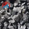
Quick Answer: A ferrosilicon 75 inoculant for cast iron is a FeSi-based treatment alloy formulated to promote graphite nucleation before solidification. It helps reduce undercooling, chill and carbide formation in gray and ductile iron. However, ordinary FeSi75 used for silicon adjustment is not automatically a qualified inoculant: performance also depends on active elements, particle size, addition method and fading time. In ductile iron, inoculation follows magnesium treatment; it does not replace nodularizing.
Key Points for Foundry Buyers
- Specify an inoculant formulation, not just "75% Si ferrosilicon."
- Evaluate gray iron by graphite structure and chill; evaluate ductile iron by nodule count, nodularity and carbides.
- Match the particle size to ladle, in-stream or in-mold addition.
- Use a batch COA and controlled foundry trials to check chemistry and casting performance.
Table of Contents
- What Is FeSi75 Inoculant for Cast Iron?
- Foundry vs. Steelmaking FeSi75: Key Differences
- How FeSi75 Inoculation Works in Cast Iron
- Calcium and Aluminium in FeSi75 Inoculants
- FeSi75 Inoculant Particle Size Selection
- Inoculant Addition Rate and Fading
- How to Verify FeSi75 Inoculant Performance
- Frequently Asked Questions
What Is FeSi75 Inoculant for Cast Iron?
A FeSi75-based inoculant is a ferrosilicon alloy used in molten gray or ductile iron to encourage graphite formation as the metal solidifies. Inoculation is normally a late treatment, carried out in the ladle, during pouring or within the mold.
The distinction is important: FeSi75 describes a nominal silicon grade, not a guaranteed inoculating performance. Ferrosilicon added to raise the silicon content of base iron may not have the controlled active-element chemistry or particle size expected of a dedicated inoculant. A foundry should therefore purchase to an agreed inoculant specification rather than selecting by Si percentage alone.
For a separate explanation of ferrosilicon used as a deoxidizer and silicon source in steel production, read our FeSi75 for steelmaking guide.
Foundry vs. Steelmaking FeSi75: Key Differences
Steelmaking FeSi75 is primarily selected for deoxidation and silicon recovery, whereas inoculant-grade ferrosilicon is selected for its effect on graphite nucleation. These are application descriptions, not two universally standardized chemical grades. The actual purchase specifications determine whether a material is suitable for either job.
| Comparison | FeSi75 for steelmaking | FeSi75-based cast iron inoculant |
|---|---|---|
| Main purpose | Remove dissolved oxygen and adjust silicon content. | Promote graphite nucleation and reduce chill or carbides. |
| Chemistry to check | Si recovery requirements and specified impurity limits. | Si plus intentionally controlled active elements, such as Ca, Al, Sr or Ba, according to formulation. |
| Particle size | Compatible with furnace or ladle alloy charging. | Matched to ladle, in-stream or in-mold inoculation equipment. |
| Acceptance criteria | Batch chemistry, size and steelmaking process requirements. | Batch chemistry and sizing plus observed casting response in trials. |
Buyer takeaway: A material labeled "FeSi75" may meet a silicon specification without being suitable for in-stream inoculation. Request the complete chemical analysis, active-element targets, screened particle-size range and relevant application information. See our FeSi75 specification and COA guide for the base-grade checks.
How FeSi75 Inoculation Works in Cast Iron
During solidification, graphite must nucleate before it can grow. Effective ferrosilicon inoculation promotes the formation of suitable nucleation substrates in molten iron. More effective graphite nucleation reduces the undercooling needed for solidification and helps shift the structure away from unwanted iron carbide (cementite). The result depends on the base iron chemistry, dissolved oxygen and sulfur, cooling rate and treatment practice-not simply on the amount of silicon added.
FeSi75 Inoculant for Gray Iron: Graphite and Chill
In gray cast iron, a successful inoculation treatment generally promotes a more uniform distribution of graphite flakes and reduces the risk of white iron or carbides, especially in thin sections that cool quickly. Foundries evaluate the result using chill wedges or thermal analysis together with metallography. Graphite morphology is also affected by carbon equivalent, sulfur level and section thickness, so the inoculant should not be credited with every change in structure.
FeSi75 Inoculant for Ductile Iron: Nodule Count
In ductile cast iron, inoculation is used after the magnesium-based nodularizing treatment to improve graphite nodule nucleation and reduce carbide formation. Common checks include nodule count, nodularity, carbide content and mechanical properties. An inoculant does not replace FeSiMg or another nodularizer: magnesium treatment establishes the conditions for spheroidal graphite, while inoculation helps provide sufficient graphite nucleation sites.
Calcium and Aluminium in FeSi75 Inoculants
Calcium (Ca) and aluminium (Al) are deliberately controlled in many ferrosilicon-based inoculants because they affect reactions with oxygen- and sulfur-bearing species in molten iron. Under suitable melt conditions, the resulting complex compounds can participate in the formation of effective graphite nucleation sites. Other formulations may use strontium (Sr), barium (Ba), zirconium (Zr) or rare-earth elements to obtain a different response.
The right composition is formulation-specific. A low-calcium, low-aluminium FeSi-based inoculant containing strontium, for example, is not inherently inferior to a calcium–aluminium formulation. Conversely, a standard FeSi75 analysis showing Ca and Al does not by itself establish satisfactory inoculation.
| Element | Why it matters | What to request |
|---|---|---|
| Si | Contributes silicon to the melt; nominal grade alone does not predict inoculation. | Agreed Si range, not only a commercial grade name. |
| Ca | Can participate in oxide/sulfide-related nucleation reactions. | Target range for the specified inoculant formulation. |
| Al | Can contribute to inoculation reactions; excessive Al can increase pinhole risk in susceptible molding conditions. | Specified range or maximum, matched to the foundry process. |
| Sr / Ba / other additives | May be intentionally added for a particular inoculation response. | Identification and ranges of any claimed active elements. |
| Other impurities | May affect the melt specification and acceptance criteria. | Application-specific impurity limits and the batch test method. |
For example, aluminium-related hydrogen pinholes can be influenced by molding-sand moisture and other melt conditions. If pinholes occur, investigate the complete process rather than attributing them to the inoculant alone.
FeSi75 Inoculant Particle Size Selection
Particle size affects feeding, dissolution and material loss. Very fine material can be difficult to handle consistently, while oversized particles may not dissolve completely during the available treatment time. A screened size distribution and control of undersize fines are therefore important parts of the purchase specification.
The ranges below are illustrative commercial inoculant sizes published for particular FeSi-based products; they are not a universal specification for all FeSi75 grades or dosing systems.
| Inoculation method | Published size examples | Main selection check |
|---|---|---|
| In-stream inoculation | 0.2–0.7 mm | Steady feeder flow and full dissolution in the stream. |
| Small-ladle inoculation | About 0.5–2 mm | Good metal contact, dissolution and minimal fines. |
| Larger-ladle inoculation | About 2–6 mm | Sufficient dissolution and mixing before pouring. |
| In-mold inoculation | Product-designed inserts or specified granules | Compatibility with the gating system and reliable dissolution. |
Technical note: These are application examples drawn from published inoculant product data, including SRF 75. Confirm the grade-specific size range, tolerance and feed behavior with your supplier before ordering.
A bulk FeSi75 lump size such as 10–50 mm should not be treated as an in-stream inoculant specification. For a general explanation of crushed and screened FeSi sizes, see our ferrosilicon particle size guide.
Inoculant Addition Rate and Fading
How Much Ferrosilicon Inoculant Should You Add?
There is no single FeSi75 inoculant addition rate that fits every foundry. Published technical sheets for specific FeSi-based inoculants show different recommendations, often within a broad range of a few hundredths to several tenths of a percent of treated iron weight. The correct rate depends on iron chemistry, casting section, inoculant formulation and whether addition takes place in the ladle, in-stream or in-mold.
Inoculant mass (kg) = treated iron mass (kg) × addition rate (%) ÷ 100
Calculation example only: at 0.10%, a 1,000 kg melt requires 1.0 kg of inoculant. This illustrates the calculation; 0.10% is not a universal process recommendation.
When trialing a new inoculant, compare it against your existing approved practice while keeping base-iron condition, magnesium treatment (if applicable), pouring temperature and sampling position as consistent as possible. Record the actual addition mass rather than a nominal set point alone.
What Causes Ferrosilicon Inoculation Fading?
Inoculation fading is the gradual loss of inoculating effect after treatment. As time passes between addition and solidification, the availability and effectiveness of nucleation sites may decrease. Long holding and variable pouring delays can therefore produce different responses between the first and last castings from a ladle.
Late inoculation-such as controlled in-stream feeding or qualified in-mold inserts-can reduce the interval before solidification, but it still requires dependable dosing and dissolution. Compare early and late pours by chill testing, thermal analysis or microstructure to judge whether fading is a real problem in your process. ASK Chemicals' foundry guidance also discusses the practical reasons for choosing late inoculation.
How to Verify FeSi75 Inoculant Performance
A COA confirms specified chemical analysis; it cannot, by itself, prove inoculation performance in your foundry. Qualification should cover both the supplied material and its behavior in repeatable trials. The checklist below connects supplier documents with casting-level acceptance criteria.
| Check | What to record | Why it matters |
|---|---|---|
| Batch COA | Si, specified active elements, agreed impurities and heat/lot number. | Confirms chemistry against the accepted formulation. |
| Screen analysis | Nominal size range, fines, oversize and sampling method. | Checks dosing and dissolution consistency. |
| Process conditions | Iron grade, carbon equivalent, sulfur, treatment temperature, addition method and elapsed time. | Allows meaningful comparison between trials. |
| Gray iron results | Chill depth, thermal-analysis response and graphite structure. | Shows whether the target microstructure improves. |
| Ductile iron results | Nodule count, nodularity, carbides and residual Mg where relevant. | Checks results without confusing inoculation with nodularizing. |
| Casting performance | Defect rate, mechanical properties and first-versus-last pours. | Tests repeatability and suitability for production. |
A Practical FeSi75 Inoculant Trial Procedure
- Define the baseline: document the current inoculant grade, addition rate, particle size and acceptable casting results.
- Control the comparison: use comparable heats and the same test-piece geometry, with key treatment and pouring conditions recorded.
- Measure outcomes: compare thermal analysis or chill results and microstructures, not just the appearance of a single casting.
- Confirm repeatability: check more than one heat or lot before changing regular production practice.
If you are comparing our standard FeSi75 supply options, see our ferrosilicon 75 product and supply page. Please confirm the required active-element ranges and application suitability with us before assuming a standard FeSi75 product is a dedicated inoculant.
Request FeSi75 for Your Foundry
Tell us whether you produce gray or ductile iron, your required chemistry (especially Ca and Al), particle size, addition method, quantity and delivery destination. We can review the requested FeSi75 supply specification and confirm what is available before quotation.
Email: sale@zanewmetal.com
Contact UsFerrosilicon 75 Inoculant: Frequently Asked Questions
Can standard FeSi75 be used as a cast iron inoculant?
Not automatically. Standard FeSi75 can supply silicon, but a dedicated inoculant requires a suitable active-element formulation and particle size. Qualify the specific material through chemical checks and foundry trials before using it for routine inoculation.
What particle size is used for FeSi75 in-stream inoculation?
A 0.2–0.7 mm range appears in published data for certain FeSi-based inoculants. The correct size depends on the feeder and dissolution time; use the supplier's grade-specific range and verify it in trial pours.
What is the FeSi75 inoculant addition rate?
There is no universal addition rate. Follow the technical sheet for the exact formulation and establish a working rate through foundry trials. For calculation, multiply treated iron mass by the percentage rate and divide by 100.
Why are calcium and aluminium controlled in inoculants?
They influence the chemistry of potential graphite nucleation substrates. Their preferred levels depend on the formulation and molten-iron conditions. Excess aluminium may also increase hydrogen-pinhole risk under susceptible molding conditions.
Does FeSi75 inoculant replace magnesium treatment in ductile iron?
No. Magnesium-based nodularizing treatment establishes spheroidal graphite formation; subsequent inoculation supports graphite nucleation and can help control nodule count and carbides.
Technical references
For technical background on graphite nucleation and chill, see Elkem's inoculation overview. For the interaction of aluminium and hydrogen pinholes, see Elkem's surface-defect guidance. Published commercial particle-size examples are linked in the particle-size section above. Exact treatment recommendations must be validated for the foundry's own process.